
Open loop gain is a crucial parameter of an op-amp amplifier. While designing the feedback network around it assuming infinite loop gain is easy to do, one, sometimes, needs to know the poles and open loop gain of the amplifier in order to do frequency compensation, or know what the out-of-band loop gain is, as it might also be important for specifications.
This article will show the solution about how to measure the open loop gain of an op-amp in an accurate and, more importantly, simple manner.
The Open Loop Gain Testbench
TL;DR: This is the solution.
A correct and simple testbench for simulating the Open-Loop Gain of an Op-Amp (in this case, the OP07) is shown in figure 1
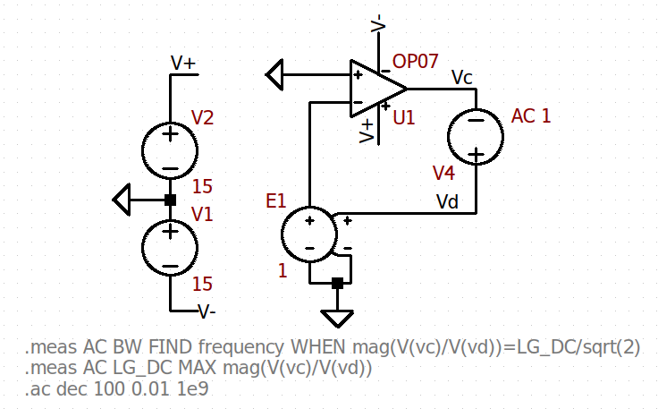
Some people might recognize this method of placing the voltage source along the feedback loop from this Linear Technology of Kris Lokere. Even though it is not metioned there, this is the Middlebrook method (published by him in ’75) with a single voltage source.
We have used an ideal voltage-controlled voltage source (VCVS) and an AC stimuli within the loop.
Why do we need a VCVS with a voltage gain of 1? Isn’t it enough without it? Since we are looking for the open loop gain, then this presumes that the amplifier is not loaded with its own feedback network or some other load. The aim is to keep a DC feedback path while not loading the output of the amplifier.
If we discarded the VCVS, then we would be measuring the loop gain of an standard Op-Amp voltage buffer. If the Op-Amp were really an ideal VCVS with a finite gain, then, using the VCVS with a voltage gain of 1 would be unnecessary. However, a real Op-Amp has a finite input capacitance and resistance. While it is true that these might only make a difference at high frequencies, it is always good to not make any assumptions and test open loop gain properly.
Another well-known Open-Loop Gain Testbench Alternative
Another possibility, as also shown in this TI training video, is as follows:
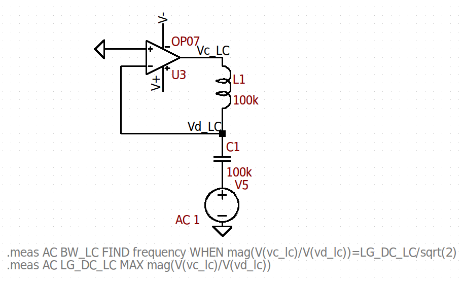
In this case, the voltage souce is placed outside the loop, but an inductor is placed to keep the loop biased at DC (in this case, the output and (-) port and output are at 0V). However, it also isolates the input (-) port and the output at AC, as it represents a very high impedacne. A capacitor is used in series with the voltage source in order to not disturb the Op-Amp biasing with the DC bias of the source.
Comparison
To prove that both TBs give out the same simulation results, we run them in LTspice and compare its frequency response and calculated low-frequency open loop gain and dominant pole.
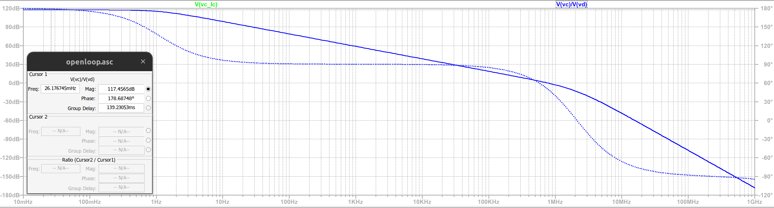
In figure 4, the dominant pole is calculated under the “bw” and “bw_lc” (for the method with L and C) variables, and the maximum open loop gain is under “lg_dc” or “lg_dc_lc”.
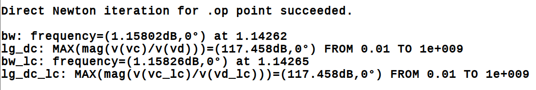
Both calculations result in 1.1Hz as a the location of the dominant pole and 117.46dB as the open loop gain at low frequencies (below the pole).
To conclude, both results are equally valid and correct. Perhaps the method with the VCVS might be sligtly simpler as it uses only 2 extra elements (besides the op-amp itself) to evaluate open loop gain, whereas the L and C method needs 3 (the L, C and voltage source). It’s not an important difference, anyhow, so both methods can be used interchangeably.
Modeling Conclusion
Since we have calculated the dominant pole location and the open loop gain at low frequencies, we can model the op-amp open loop gain formula as: \[\begin{aligned}
A_{OL}(s) = \frac{746.448k}{1+\frac{s}{2\pi1.1Hz}}
\end{aligned}\]
To verify this claim, we model the op-amp open loop gain with a VCVS source in ltspice, as shown in figure 5.
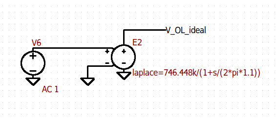
We run an AC simulation and overlay this open loop gain with the previous measured result, results are shown in figure 6.
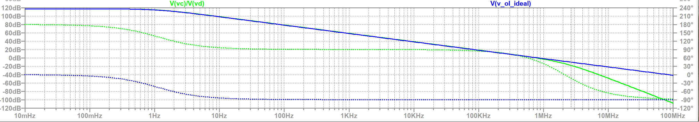
The blue curve in figure 6 is the ideal model. Obviously, we have only come up with a 1st-order model, as there’s a second pole below the 0dB line that has not been model. Therefore, we can claim that our model is good enough to 1st-order.
2 thoughts on “Simulating Open Loop Gain”
Other than your last statement that says the approach is accurate only to first order, I disagree with everything you say here and I encourage you to stop promoting these approaches.
The reason why is that most people do not understand that these approaches are approximate are only suitable for estimating open-loop gain. Specifically these approaches cannot be used for computing loop gain, which is needed to determine the stability of the loop. In my experience, it is loop gain and stability that most people are interested in.
Even the concept of open-loop gain has low value. It has some value when talking about the op-amp in isolation, but it should never be employed when talking about an op-amp in a closed loop.
The fundamental issue with these approaches is that they alter the circuit, and therefore change any loading effects and may block reverse transmission through your probe. As a result they give reasonable results at low frequencies, but results near the unity gain frequency are way off.
It would be better to promote the approaches by Middlebrook or Tian (https://sites.google.com/site/frankwiedmann/loopgain). Or you could promote the approach described in Gray and Meyer.
Thanks for your constructive feedback, Kent. I’m flattered someone like you took the time to comment in my incipient site.
My aim here has nothing to do to with assessing loop stability and only deals with finding out the open-loop transfer function of the Op-Amp in isolation, as illustrated by the first picture (perhaps my mention of the LTspice video caused some confusion and made it look like I wanted to assess loop stability, I’ll try rewording that part).
To that aim, I put the Op-Amp in a feedback loop to keep the biasingand ideal VCVS so that that the Op-Amp’s output isn’t loaded by the input capacitance, but I never claim I’m assessing loop stability in such a way. How could I? It’d be complete nonsense to make such a claim.
Whether it has little value or that few people are not interested in this is a fair discussion. However, I was particularly interested in this, and had seen questions on the internet about how to find the open-loop gain and such. If someone wanted to understand the components making up the loop gain, I could see how finding out the the AOL would be useful for that.
I’m fully aware of the Middlebrook and Tian methods for assessing loop stability and that the old Middlebrook method doesn’t account for reverse transmission whereas the new one does. I’m also aware of an IEEE TCAS2 paper published last year that claimed the Tian method is not entirely correct, but I haven’t had the time to go through it yet. Have you gone through it? https://ieeexplore.ieee.org/document/10149201
I plan to write some articles in the future about the old Middlebrook method just to start simple 🙂